


Faq's and support
Chargers
Battery Chargers
How do you connect batteries and chargers in series and parallel?
Learn all about connecting batteries in series and parallel at batterytender.com/series-parallel.
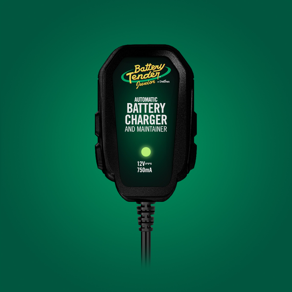
How is the Battery Tender® Junior battery charger different from a trickle charger?
The Battery Tender® Junior battery charger has microprocessor controlled power electronic circuitry which enables it to preform and safely control a number of sophisticated charging functions, well beyond the capability of inexpensive trickle chargers. Some legacy marketing literature refers to the Junior as a “Trickle Charger with a Brain”. That description was based in context on two parts, first the relatively low output current, and second, the reduced level of charge control sophistication on earlier Junior models relative to the Plus. Since mid-2006 the only major functional difference between the Junior and the Plus is the maximum amplitude of the charger current, 0.75 and 1.25 amperes, respectively. Even though the marketing description may still be applicable, again, in a limited context, we can say now that the Junior has a larger brain that enables it to create maximum charge effectiveness with minimal output current amplitude.
After connecting the Junior to a battery and then applying AC power, it first conducts a number of checks during Initialization Mode to ensure that the battery functioning normally. Then it will deliver its full charge at a constant rate of 0.75 amperes. This is called the Bulk Charge Mode. The battery voltage will rise and when it reaches a predetermined level the Junior will hold the battery charge voltage constant at that level, allowing the charge current amplitude to drop. This is the Absorption Charge Mode. The Absorption Charge Mode is complete when the battery charge current drops below a very low value, usually below 1/8 ampere. Some Junior models have timers to limit the duration of the Absorption Charge Mode.
After the current drops or the allotted time expires (typically several hours), the Junior automatically switches to a Float / Maintenance Charge Mode. The purpose of the Float / Maintenance Charge Mode is to maintain the battery voltage just slightly (typically between 1/10 and ½ volt) above where it would be if it were fully charged and sitting at rest. This keeps the battery topped off at voltages well below the gassing voltage of a lead acid battery.
Based on price alone, trickle chargers often appear to be a better economic choice for the typical consumer, but trickle chargers do not have the advantage of sophisticated electronic control. Therefore, as they allow the value of charge current to trickle down to what appears to be safe levels, the output voltage of the charger may very well rise to an unacceptably high level, sometimes even going higher than 16 VDC depending on the charger type and the battery that is connected to it. This magnitude of voltage is far above the gassing voltage of a lead acid battery. If the battery remains connected to this high level of voltage for an extended period of time, extreme damage may be done to the battery. Without Battery Tender® type electronic safety controls, what appears to be an initial cost savings for the charger may actually cost several times the charger price in replacement batteries.
Is the Battery Tender® Junior battery charger more expensive than a trickle charger?
There is a good chance that the Battery Tender® Junior. will cost no more or maybe even less than some trickle chargers presently on the market. Even if the Battery Tender Junior. does cost more, it will not be much more. With the performance improvements designed into the Junior since 2006, the total cost of ownership should be much less. The Junior is now essentially a lower power version of the Battery Tender® Plus. Considering that you will avoid the likely dramatic reduction in battery life resulting from using a trickle charger, the Junior will more than make up the difference in price by extending the useful life of only one engine start battery. The Battery Tender Junior. comes with a 5 year limited warranty.
Deltran Connected App
What happened to the Deltran Connected App?
The Deltran Connected app, which provided wireless monitoring for select Battery Tender® products, has been discontinued and is no longer supported. As a result, the app will no longer function, and WiFi connectivity is no longer available for chargers that previously included this feature.
Why was the app discontinued?
To continue providing the best battery charging solutions, we made the decision to remove WiFi connectivity from our chargers and discontinue the Deltran Connected app. This change allows us to focus on the reliability and performance of our core products.
What does this mean for my product?
For Battery Tender WIFI-enabled chargers: The charger itself continues to function as designed, delivering the same trusted performance—it simply no longer connects to the app.
For the Wireless Battery Monitor: This product relied on the Deltran Connected app for data display, so it is no longer functional.
What are my options?
We understand that this may be disappointing news. While the app is no longer available, we stand by our products and appreciate your loyalty. If this change impacted your Battery Tender product, please reach out to support@deltran-global.com.
Battery Charger Accessories
How are the BatteryTender® Plus and Junior battery chargers different from other automatic battery chargers?
Many automatic battery chargers simply turn off when the battery voltage rises to a preset level or when the charge current falls below a certain level. With the battery sitting idle, its internal losses will consume much of its stored charge. Depending upon the age and condition of the battery, it may only take a couple of months before the battery loses more than 90% of its charge. The amount of charge lost tracks pretty well with the reduction in battery terminal voltage.
Some automatic chargers will restart when they sense that the battery voltage is too low. As a battery goes through these types of cycles of repeated charging and idle self-discharge to low capacity levels, the useful battery life may be dramatically reduced.
Both the BatteryTender Plus & Junior battery chargers do not turn off after they charge the battery. They automatically switch to a safe float voltage level that keeps the battery charged and yet does not do any harm to the battery. In fact, in most cases, this type of charge maintenance will extend the battery’s useful life by at least 50%.
Some customers have reported battery life increases of more than double what they had before using the Battery Tender Plus or Battery Tender Junior battery chargers.
Is the Battery Tender® Plus battery charger more expensive than a trickle charger?
In simple terms, comparing only the “off-the-shelf”, retail price dollars, probably yes. However, in terms of the total cost of ownership, including the likely dramatic reduction in battery life resulting from using a trickle charger, then the answer is ABSOLUTELY NO. The Battery Tender® Plus will more than make up the difference in price by extending the useful life of only one engine start battery. Multiply this savings over the 10 year Deltran warranty period and you will save enough in battery cost to more than pay for the Battery Tender® Plus battery charger.
How long can I leave the Battery Tender® Plus battery charger connected to a battery?
In theory, you can leave the Battery Tender® Plus battery charger connected to a battery forever. That’s a really long time. Sales people like to say, “Just plug it in and forget about it!” However, practically speaking, it is a good idea to check on the battery at least once every couple of weeks. Strange things can happen. Sometimes a battery can have a weak cell that won’t show up until the worst possible time. Of course, that time is usually when the battery is connected to a charger, and you are out of town on vacation.
If something goes wrong, then you have to deal with the question of the chicken and the egg. Which came first? Did the battery fail because it was connected to the charger or did the charger fail because it was connected to the battery? Good luck sorting that one out.
With a battery and a charger connected together, it’s a much better idea to be proactive and anticipate problems, however unlikely they may be. In more than 99.9% of cases, nothing will go wrong. That still leaves about 0.1% where something might. Learn to respect electricity. A little common sense can go a long way.
Also consider this. No matter how good a product is, anything can break. In fact, everything will break, eventually. There are only 2 questions to be answered. 1) When will it fail? & more importantly 2) How will it fail? If a product is designed and built well, a manufacturer will set a long warranty period, usually several years, to support that notion. Deltran, and other responsible manufacturers, invest a tremendous amount of time, effort, and money to ensure that their products will fail in a relatively safe manner. For electronic products, at the very least that means no electrical shock or fire hazard.
The Battery Tender® Plus battery charger has a 10 year limited warranty, which is unprecedented among battery charger manufacturers. And it is listed with Underwriter’s Laboratories to comply with both US and Canadian electrical product safety standards for battery chargers used with engine start batteries.
Can the Battery Tender® Plus battery charger be used to charge more than 1 battery simultaneously if the batteries are connected in series?
Yes, but series connections have more restrictions than parallel connections. A series connection means that positive post of one battery is electrically connected to the negative post of the next battery, and the positive post of that battery is connected to the negative of the next battery and when all the connections are made, the positive post of the last battery and the negative post of the first battery becomes the connection point for the entire battery pack. The voltage of a series connected battery pack is sum of the voltage of each battery in that pack. So if two 6 volt batteries are connected in series, then the voltage of the battery pack is 12 volts.
There are more restrictions on charging battery packs connected in series than there are for parallel connected battery packs. The nominal battery voltages (i.e. 12V, 8V, 6V, 4V, 2V) must be the same on each battery, and the batteries must be the same lead acid type (flooded, AGM, or Gel Cell). Also the batteries must be close to the same size in terms of amp hour capacity, and they must be close to the same level of discharge. It is also a good idea that the batteries be approximately the same age and that they be in relatively the same general condition.
If all 4 of these conditions are met, and if the total voltage of the pack is 12 volts (or 8 volts, or 6 volts depending upon the Plus model), then yes, the Battery Tender Plus battery charger can be used to charge more than 1 battery simultaneously when those batteries are connected in series. This will not work if the total battery voltage is greater than the voltage of the Battery Tender Plus (12V, 8V, or 6V).
Can the Battery Tender® Plus battery charger be used to charge more than 1 battery simultaneously if the batteries are connected in parallel?
Yes, but with restrictions. A parallel connection means that positive posts of each battery are electrically connected together and the negative posts of each battery are electrically connected together. The voltage of a parallel connected battery pack is exactly the same as the voltage of each battery in that pack.
If the nominal battery voltages (i.e. 12V, 8V, 6V) are the same on each battery, and if the batteries are the same lead acid type (flooded, AGM, or Gel Cell), then yes, the Battery Tender® Plus battery charger can be used to charge more than 1 battery simultaneously when those batteries are connected in parallel. Just remember that 2 batteries in parallel behave like one large battery. The charge storage capacity of each battery simply adds together. Two 12 volt batteries, each with 25 amp hour capacities, will look like one 12 volt battery with a 50 amp hour capacity. You may be able to charge more than 1 battery simultaneously, but it will take longer
Can I leave the Battery Tender Plus® battery charger connected to a battery while I’m using the battery to power another appliance like a radio?
Actually, this is basically the same situation that exists by default on many of today’s complex, computer controlled vehicles that have a wide range of on-board electronic devices, many of which consume electric power even when the vehicle is not running. So the short answer is ‘Yes, you can leave the Battery Tender Plus battery charger connected to a battery even when it is being used to provide power to another appliance. However, this is definitely not a simple yes or no type of question. There are definitely some things to consider that may limit this type of usage.
Think about how consumer electronic products are used and consequently, how they are designed. To keep the price low and competitive, it is important to limit the battery charger applications to a realistic, manageable portion from the vast number of ways in which a battery charger may be used.
The simplest applications involve charging and maintaining vehicle engine start batteries. The advantage in this application is that there is almost always another, larger source of electric power to charge the battery while the vehicle is running. So the off-line engine start battery charger need not normally supply the full amount of charge stored by the battery. One common exception would be when the vehicle battery is drained because lights were left on.
The point is that the engine start battery charger is not normally expected to deliver its maximum charge current for extremely long, extended periods of time.
Is there any danger that the Battery Tender® Plus battery charger can cause any damage to other automotive electronic systems while it is connected to the battery in my automobile?
No. As long as the automotive electronics system is functioning properly, there should be no problem. Typical automotive electronic systems run on the alternator output of approximately 14 to 15 volts. The maximum charge voltage output of the Battery Tender® Plus battery charger is in the same range and less than 15 volts. For the majority of the time, the Battery Tender® Plus will be operating in float / maintenance mode so the maximum voltage output will be less than 14 volts.
How is the Battery Tender® Plus battery charger different from the Battery Tender battery charger?
OVERVIEW and COMPARISON: The Battery Tender and Battery Tender Plus battery chargers are both designed to provide a quick, economical means to recharge motorcycle and engine start batteries used in other power sports equipment. Typically, power sports engine start batteries are in the 12 Ah to 20 Ah capacity ranges. Both chargers are constant voltage type with precisely regulated output current limits. Both chargers have a regulated, nearly constant 1.25-ampere output charge current during the bulk charge phase. Physically, there is virtually no difference between these 2 chargers. Both the Battery Tender and the Battery Tender Plus operate in 3 charge modes, bulk charge, absorption charge, and float charge.
Both the Battery Tender® and the Battery Tender® Plus are 4-step chargers meaning that they operate in 4 charge distinct modes: initialization, bulk charge, absorption charge, and float / maintenance charge. The legacy marketing literature and the operating instructions do not identify the original Battery Tender® as having an initialization mode. Therefore there is a lot of old literature that refers to Battery Tender® chargers as 3-step chargers. However the basic initialization functionality was present but there was no LED status indication; the Battery Tender® simply would not allow output voltage to activate unless a battery was properly connected to the charger. The Battery Tender® Plus does have an LED indication to indicate a faulty battery connection, which, with a little extra software and battery checks, completes the mechanization of ‘initialization’, the 4th charging step, even though time sequentially it is actually the 1st step.
RECHARGING AGM BATTERIES: The Battery Tender® has an absorption charge mode, but the the Battery Tender® Plus has a different absorption mode maximum charge voltage and a timer to hold the absorption voltage longer. These specific changes were made to accommodate the charging requirements of Absorbed Glass Mat (AGM) style lead acid batteries.
Can the Battery Tender® Plus successfully perform the initial charge on a new, flooded, motorcycle battery?
Background: The motorcycle dealers receive batteries from the manufacturer in a dry state. The plates are dried out, and there is no acid in the cell compartments. (Do not confuse this with a dry-cell battery.) The dealer must fill the individual battery cells with acid and then put them on a shop charger to pre-charge prior to selling them to a customer. As the batteries arrive from the manufacturer, the plates are approximately 80% "formed". The initial pre-charge, post-formation charge, or more correctly, formation-finishing charge, must be conducted at a specific power level and for a specific time period. Each manufacturer has its own recommendations, for example one manufacturer recommends that the charger deliver a constant current equal to 10% to 15% of the battery amp-hour capacity and that the charge current be applied to the battery for a period of 5 to 10 hours.
Answer 1) Certainly if the dealer has properly pre-charged the battery after filling it with acid, then the answer is ABSOLUTELY YES.
Answer 2) If the dealer has not properly pre-charged the
newly filled battery prior to the sale, then the answer is YES, WITH SOME QUALIFICATIONS:
Qualification A) The Battery Tender® Plus should be left on the new battery for a minimum of 24 hours on float, in addition to whatever amount of time it takes for the charger to get to the float stage. It is not clear how to correlate the 80% formed plates with a given state of charge once the cells are filled with acid. To be safe, assume that the batteries require a full 100% charge after the cells are filled.
For example, a 16 Ah battery will take about 13 hours to get to the absorption voltage (constant 14.4 Volts). It may take another 6 to 8 hours to reach the float voltage (constant 13.2 Volts). This may sound awkward; because what happens is that the battery charge current drops while the absorption voltage is held constant. When the battery current drops to 0.1 amp, or if 6 to hours have elapsed at the absorption voltage, the charger automatically switches its output from 14.4 V to 13.2 V. So it may take the better part of 20 hours to reach the float stage. Add another 24 hours to that and you are at 44 hours. Throw in another 4 hours for good measure and you get a nice round, even 48 hours, or 2 days.
Qualification B) Although there are probably several charging methods that will be equally effective, regardless of who manufactures the battery, in the interests of technical consistency, they will not officially sanction any initial charging method other than those published in their technical applications literature.
How can the Battery Tender® Plus battery charger that is rated at 1.25 amperes recharge a battery as fast as another charger that is rated at 3 amperes?
Short Answer:
Deltran’s claim that the 1.25 amp Battery Tender Plus battery charger will charge a battery in the same amount of time as a typical 3 amp charger is based on the fact that the Battery Tender Plus charge current is very nearly constant during the bulk charge period, while a typical 3 amp charger, configured like so many chargers on the market, is not.
Detailed Answer:
You would think that a 3 amp charger would recharge a battery roughly 3 times faster (actually only 2.4 times faster) than a 1.25 amp charger. There are 2 main reasons why this is not true.
First, the way a battery reacts to charge current is complex. The simplest approximate calculations for recharge time only work for about the first 75 or 80% of the charge and only if the charge current is nearly constant. Returning the last 20 to 25% of the charge to the battery is also a complex and time consuming process. It may very well take as long to return the last 20% of the battery charge as it took to return the first 80%.
Second, and just as important, is the way that battery charger manufacturers rate the output current of their charger products. Let’s say that the 3 amp rating is based on a peak current value during the initial charge phase and the 1.25 amp rating is nearly constant for entire time that it takes to return 80% of the battery charge. Let’s also say that the 3 amp current only exists long enough to return 10% of the battery charge and then it tapers down to 1 amp for the next 70%.
The dimensions or units describing electrical charge are the Coulomb or, more conveniently in the context of battery charging, the Amp-Hour. The abbreviation for amp hour is Ah.
A battery charger delivers charge (amp-hours) to the battery by using an electrical current (Amps) at its output over a period of time (Hours). The numerical product of the electrical current and time period is the amount of charge delivered. This is true in a general sense for any charger.
Now let’s do some math. For a 100 Ah battery, 10% = 10 Ah, 70% = 70 Ah, and 80% = 80 Ah.
10 Ah / 3 A = 3.3 Hours, 70 Ah / 1 A = 70 Hours, So this particular 3 amp charger takes 73.3 hours to return 80% of the charge to a 100 Ah battery that was fully discharged.
80 Ah / 1.25 A = 64 Hours, so a nearly constant 1.25 amp charger (that would be the Battery Tender® Plus) takes only 64 hours to return 80% of the charge to a 100 Ah battery that was fully discharged.
Marketing and sales people like big performance numbers because they believe that those numbers enhance the perception of value. The truth is that the best value for a battery charger should be based on the total cost of ownership for both the charger and the batteries that it is charging and maintaining. If a charger has a smaller output current rating, but recharges the battery in less time, and if it maintains the batteries in a full state of charge by employing a float / maintenance function those are both good things help to make the batteries last longer. Of course, the Battery Tender® Plus does both of those things very well.
What happens if the AC power is removed from the Battery Tender® Plus battery charger while it is connected to a fully charged battery?
If the battery is fully charged, then the Battery Tender Plus battery charger’s green light will be on. Once the AC power is removed from the Battery Tender Plus battery charger, the green light will go out and the charger not have any effect on the battery. The Battery Tender Plus battery charger is protected from reverse current, so it will not discharge the battery. Of course, like we said earlier when discussing nominal voltage mismatches between a battery and a charger, the battery will not be recharged either.
When AC power is restored to the Battery Tender Plus battery charger, it will restart its charge cycle. The sequence of events should go something like this. The red light will come on for a few minutes. Then the green light will start flashing while the red light stays on. The next thing that happens is what may confuse some people who use the Battery Tender Plus battery charger. Remember, the battery was fully charged, so you may ask, “Why doesn’t the green light just come right back on?”
The reason that the green light doesn’t come on immediately is that when the charger first comes on, the battery is sitting there, fully charged, at a voltage of about 12.9 volts. The charger immediately tries to bring the battery voltage up to about 14.5 volts. This takes a finite amount of time, although it should only be a few minutes if the battery is fully charged. Then, when the battery reaches 14.5 volts, the charger will hold it there until one of two things happen. Either the battery charge current will drop to less than 0.1 amp (from an initial value of 1.25 amps) or, if the current does not drop below 0.1 amp, then the charger will hold the battery voltage at 14.5 volts for 6 to 8 hours.
There are a couple of reasons why the battery current may not drop below 0.1 amp. First, on a larger battery, like an automotive SLI battery, the internal losses of the battery may consume more than 0.1 amp. Second, if the vehicle or the system that the battery is connected to has appliances that consume electricity, then that consumption of electricity, coupled with the battery internal losses may very likely exceed the 0.1 amp limit. This second cause is very common and its result is that the Battery Tender Plus battery charger’s timer circuits will be fully engaged. So it will take 6 to 8 hours for the green light to come on. Fortunately, the Battery Tender Plus has the ability to continue to supply its full current even after it has switched over to the lower, float, maintenance charge voltage of 13.2 volts. When the charger turns the green light back on, it also drops its output voltage to this float, maintenance charge level of 13.2 volts.
Note: It only takes a momentary AC power outage to cause the Battery Tender Plus battery charger to reset.
HAVE ADDITIONAL QUESTIONS?
Contact Us
If you have any questions about your recent purchase or need help finding the perfect charger, our dedicated customer service team is here to assist you. We're committed to helping you get the most out of your Battery Tender products.